The Crown Pumping Engine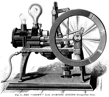
An illustration of the flywheel side of the Crown Pumping Engine. |
||
|
|
||
|
The following article was written when the Crown engine was NEW!
The Crown Gas Pumping Engine
Our illustrations (Figs. 1 and 2) represent respectively perspective and sectional views of a gas engine made by the national Meter Company, of 51 Chambers Street, New York, and adapted specially for pumping. In several of its forms the gas engine has measurably solved the pressing demand of many of the industries for a compact and a efficient motor for small powers which should be less expensive than steam and at the same time free from the objectionable features, which, in many situations debarred the introduction of the steam engine. The correctness of this view is demonstrated by the enormous extension of the introduction of this class of machines within the last five years or so.
| ||
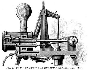 The details of the construction of the "Crown" gas engine, which will appear in Fig.2 are about as follows: The engine frame is supported on two legs above the base to make room for the pump b. The engine cylinder is placed horizontally, and the motion of the piston is communicated to the pump through the bell-crank lever c, and the vertical rod connecting with the pump piston. A connection rod unites the crank a with the lower end of the rocking arm. In the back of the power piston there are two springs, furnished with a central guide ring, into which the end of the piston rod enters. The piston rod is held against its seat by the pressure of a spring bearing upon the end of a steel pin inside the rod. The pump cylinder is made of composition, the valves being of the best rubber composition for water valves. The water is forced or lifted through a cored passage in the frame to the chamber l in the cylinder, whence it escapes through the passage k, the air chamber equalizing the flow. The charge of air and gas to the power cylinder is admitted through the intervention of two valves d and e, both solid, and so accurately fitted as to require no packing. The gas supply valve e also regulates the flow of gas to the lighter jet at g for igniting the charge. The instant the flow of air and gas to the cylinder stops, the valves close and the charge is ignited. The valves receive their motion from the main shaft through independent eccentrics. Their action is simple and positive, and they have no parts to work loose or get out of adjustment. The gas supply is received through the pipe f. The engine is supplied with a fly-wheel to insure steadiness of motion. It is exceedingly compact, occupying only 8X21 inches of floor space, and being only 17 inches high. Its total weight is 100 pounds.
From the foregoing description, the extreme simplicity which characterizes the construction of this compact and convenient form of motor will be apparent. As regards its economy for the particular service to which it has been adapted in the case here under consideration, we have the assurance that the size here shown has a capacity of raising 200 gallons of water 50 feet high per hour, at a cost of one and three-fifth cents -- estimating gas to cost $2 per M. The cleanliness, safety and economy of the gas engine, as we have remarked at the outset, are qualities that are rapidly gaining its introduction for many varieties of service, especially for small powers, and in situations where the steam engine would be inadmissible. For the special purpose of pumping water, it would appear to be particularly well adapted, as our readers have concluded from our description. The same makers are preparing to construct gas engines for miscellaneous and special uses, of all sizes, from that capable of driving a sewing machine, and upwards. The engine here described may be seen in operation at Chase's, No. 12 Cortlandt Street, New York. |
||
Back up one page
click RIGHT HERE
... or...
<-- Go back to the MENU
or......
![]() Go to Gene's Tractor Page
Go to Gene's Tractor Page